TM 5-3800-205-10-2
ADVANCED MACHINE OPERATION AND JOB SITE MANAGEMENT
GUIDELINES - CONTINUED
0006 00
MACHINE SERVICES AND CONFIGURATION CHANGES/ADJUSTMENTS - CONTINUED
NOTE
Cutting edge assembly is available as an Additional Authorization List (AAL) item (WP 0024 00).
Four personnel are required to install cutting edge assembly.
Unit Maintenance assistance is required.
a.
Park machine on firm level ground. Lower tank to the ground, apply parking brake, place transmission in N (Neu-
tral) and lock, and shut down engine. Block wheels.
b.
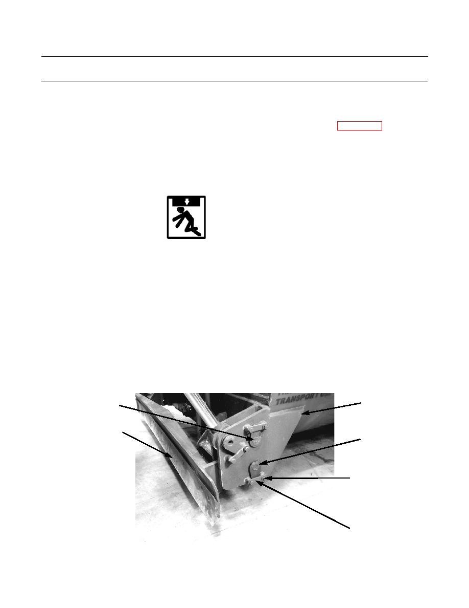
Remove four bolts from mounting bracket on each side of tank.
WARNING
Cutting edge assembly weighs approximately 300 lb (136 kg). Use extreme caution when handling heavy
parts. Provide adequate support and use assistance during procedure. Ensure that any lifting device used is in
good condition and of suitable load capacity. Keep clear of heavy parts supported only by lifting device.
Failure to follow this warning may result in injury or death to personnel.
c.
Use a suitable lift to position cutting edge assembly between mounting brackets at bottom front of tank. Line up
top pin holes and install pin, retainer bar, two washers, and bolts at each end of cutting edge assembly.
WARNING
Stand clear of cutting edge assembly while tank is being raised. Failure to do so could cause serious injury.
d.
Start engine and have machine operator raise cutting edge assembly off ground by raising tank, while two assis-
tants install bottom pins as holes line up.
e.
Secure bottom pin on each end of cutting edge assembly with retainer bar, two washers, and bolts.
f.
Tighten all eight bolts.
INSTALL TOP
MOUNTING
PIN FIRST
BRACKET
CUTTING EDGE
ASSEMBLY
BOTTOM
PIN
BOLTS AND
WASHERS
RETAINER
BAR
390-1400
0006 00-3


