TM 5-4610-223-12
f.
Installation.
(1)
Position aspirator manifold (13, fig. 4-61) over erdlator tank and connect two halves of the union (6).
(2)
Install straps (4), lockwashers (9), and screws (8).
(3)
Screw gage (6, fig. 4-62) in elbow (7).
4-84. LOW WATER LEVEL ALARM FLOAT VALVE.
a.
Removal.
(1)
Disconnect float lever (3, fig. 3-34) from lifter (6) and connecting link (10). Remove lifter (6) and
connecting link (10) from valve (8).
(2)
Disconnect elbow union (9) from nipple (11) and remove elbow with union from nipple (7).
(3)
Remove nipple (7) from valve (8).
(4)
Swing valve assembly and piping downward to allow room for unscrewing the valve (8).
(5)
Remove valve from other nipple (7).
b.
Disassembly.
(1)
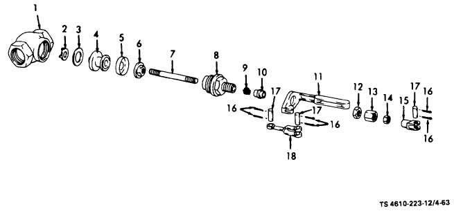
Unscrew bonnet (8, fig. 4-63) from body (1).
Figure 4-63. Low Water Level Alarm Float Valve, Exploded View.
4-135