TM 10-4610-240-10
TM 08580C-10/1
T.O. 40W4-13-21
(3)
Remove new R.O. element (4) from sealed plastic bag or element container.
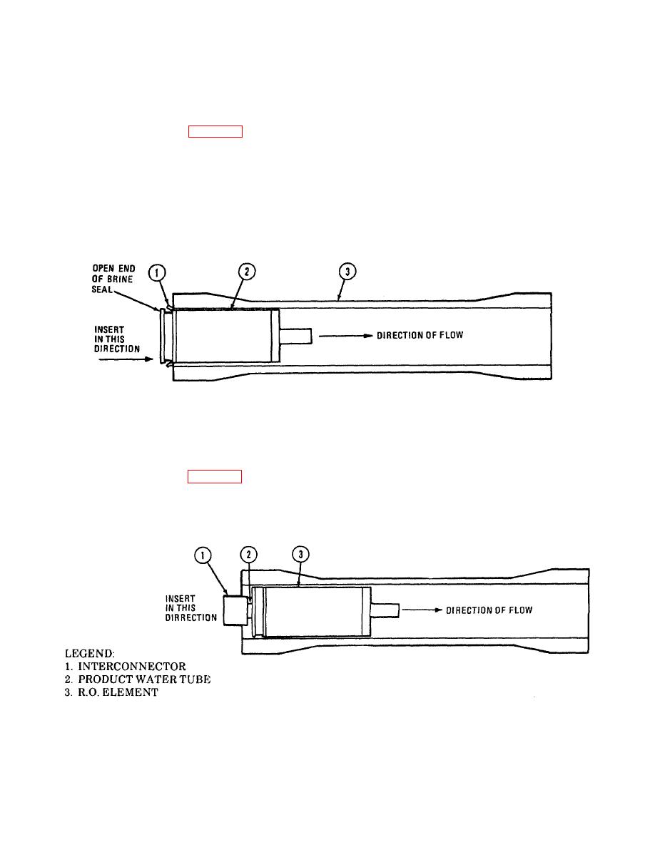
(4) Refer now to figure 3-6, and install brine seal (1) in groove of R.O. element (2) making sure open end
faces R.O. pump end of ROWPU.
NOTE
MC and AF Models top and second from bottom vessels have reverse flow direction. Open end of brine
seal should face opposite the direction of flow.
(5)
Insert by hand the first R.O. element (2) into R.O. vessel (3) until brine seal (1) touches end of R.O.
vessel.
LEGEND
NOTE
1. BRINE SEAL
(MC) Direction of flow is indicated on the side of each R.O. vessel
2. R.O. ELEMENT
3. R.O. VESSEL
FIGURE 3-6. ELEMENT INSTALLATION
(6)
Refer now to figure 3-7. Place interconnector (1) on product water tube (2) of first R.O. element (3).
NOTE
Do not confuse interconnector with end connectors. End connectors have a lip on the inside.
FIGURE 3-7. ELEMENT INSTALLATION
3-21


