extend timing
10.
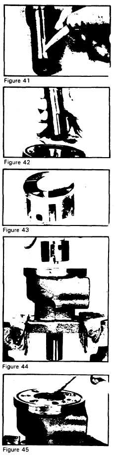
Using chalk or marking pencil, ex-
mark
tend the timing mark that is on
the end of coupling shaft (11) up
the side of the coupling shaft so
that the timing mark location will
be visible for alignment purposes
when the coupling shaft is
assembled into the housing held in
the vise. SEE FIGURE 41.
install coupling
11.
Be-sure that a generous amount of
shaft
clean wheel bearing grease is
applied to housing bearing (19)
then install coupling shaft (11)
into housing (15) seating it against
thrust washer (13). SEE FIGURE
42. The coupling shaft must rotate
smoothly on the thrust bearing
package.
insert new
12.
Insert new drive pin (10) if it was
drive pin
removed, into the commutator (9)
drive pin hole until it bottoms out.
SEE FIGURE 43.
install commutator
13.
Install commutator (9) assembly
assembly
into housing (15) commutator
bore. SEE FIGURE 44, The com-
mutator must not be cocked as it
enters the bore and the drive pin
(10) must be in line with the
coupling shaft (11) commutator
drive pin slot indicated by the
timing mark. Engage the drive pin
(10) protruding from the com-
mutator into the coupling shaft
drive pin slot, rotating the
coupling shaft if necessary. The
commutator must be below the
housing wearplate surface when
correctly seated. SEE FIGURE 45.
NOTE
NOTE: The commutator drive pin
(10) and coupling shaft (11) drive
pin slot, at this point in the
assembly, are visible through the
commutator center cavity for
coupling pin engagement purposes
in addition to the timing mark.
CAUTION
CAUTION: Do not force com-
mutator into bore. It is a close slip
fit and must rotate.
19