TM 10-4610-310-14
0102 00
PUSH-PULL SWITCH (EMERGENCY STOP) (SW9) - continued
Installation
1. Insert push-pull switch through cutout in panel.
2. Install lock nut over push-pull switch.
3. Tighten lock nut securely.
4. Connect two wires to connections on push-pull switch. Observe number tags and prior notes for proper
connection.
5. Install inner panel over push-pull switch wiring. Install eighteen screws. Tighten securely.
HANDLE MECHANISM
See Figure 3 and Figure 4 for internal components in the control module.
Removal
1. Open enclosure door for access to rear of handle mechanism.
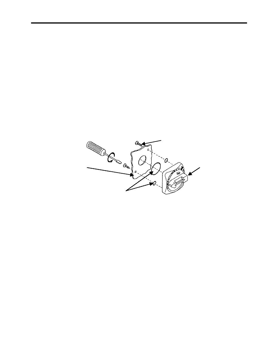
2. Remove two screws and O-rings from rear of handle mechanism. See Figure 2.
SCREW
(2 PLACES)
ENCLOSURE DOOR
HANDLE
O-RINGS
Figure 2. Handle Mechanism.
3. Remove handle mechanism from enclosure door.
Installation
1. Install handle mechanism on enclosure door of control module. See Figure 2.
2. Place O-rings in position in handle mechanism.
3. Install two screws through handle mechanism. Tighten securely.
4. Close enclosure door to make sure the handle can be turned back and forth to interface with depth shaft.
CIRCUIT BREAKER (CB1)
Removal
1. Make note of wire numbers on circuit breaker for ease of reinstallation. See Figure 3.
2. Remove wires from circuit breaker CB1.
3. Remove two slotted screws from circuit breaker.
4. Remove circuit breaker from mounting panel.
5. Remove depth shaft assembly from circuit breaker by removing the two mounting screws.


