TM 10-4610-310-14
0119 00
VALVE ADJUSTMENT CONTINUED
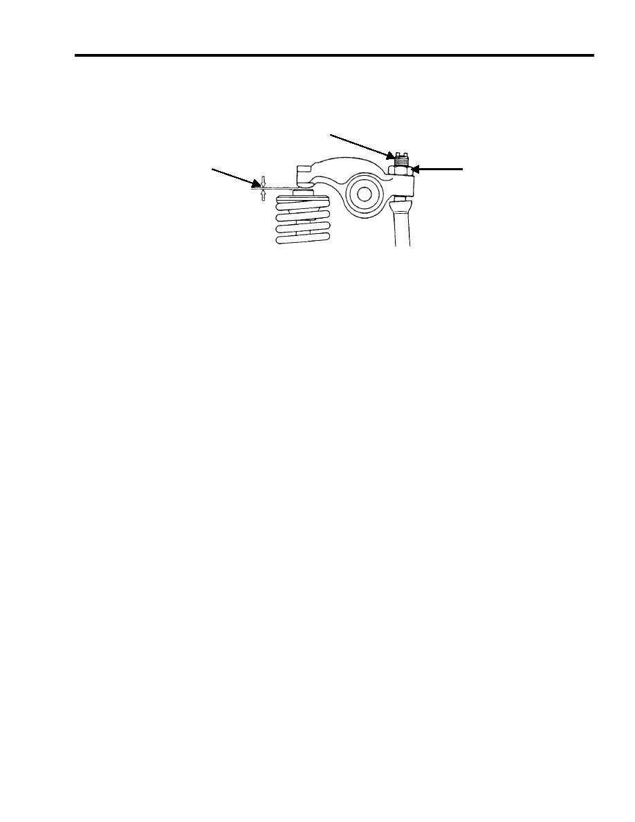
3. Loosen the lock nut. Rotate the adjusting screw in either direction to achieve proper clearance. See Figure 4.
ADJUSTING
SCREW
VALVE
LOCK
CLEARANCE
NUT
Figure 4. Valve Clearance Adjustment.
4. Tighten the lock nut. Recheck the clearance. Readjust if necessary.
5. Install valve cover, gasket and three bolts.
END OF WORK PACKAGE


