TM 5-3800-205-10-2
OPERATION UNDER USUAL CONDITIONS - CONTINUED
0005 00
TRAVELING - CONTINUED
7.
Select gear speed for downgrade that is same as gear speed needed for similar upgrade.
8.
If machine starts to slip when traveling across a hillside, turn machine to downhill side. Turn machine to downhill side
whenever machine is unstable.
WARNING
When loaded and traveling across a hillside, reduce speed significantly BEFORE turning uphill. Uphill turns
made at high speeds may cause tank to roll over, especially if tank if less than two-thirds full. Failure to fol-
low this warning may result in injury or death to personnel or damage to equipment.
9.
When loaded and an uphill turn is required, turn uphill ONLY with caution by making a wide turn at a very slow speed.
10.
In the event of a brake failure, drop the tank to aid in stopping machine.
11.
If machine becomes stuck when traveling with load, perform the following to break free:
a.
Raise tank to maximum height.
b.
Move machine forward or back, while at the same time steering in quick succession, first sharp left, then sharp
right, etc. This technique is called "duck walking".
SPRAYING OPERATION (UPPER SPRAY BAR)
WARNING
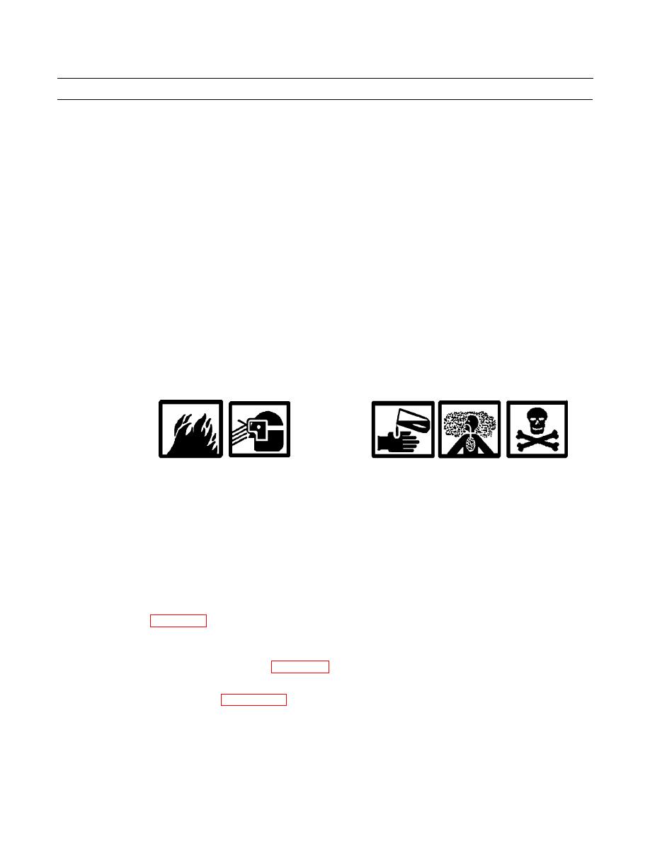
Do NOT spray or handle any substance, without first reading manufacturer's handling precautions as
printed on label. Wear appropriate protective gear, as required by MSDS and safety and medical person-
nel. Do NOT increase concentration of substance used. Do NOT smoke, as some compounds may be
flammable. Failure to follow this warning may cause injury or death to personnel or damage to equip-
ment.
NEVER drink water contained in water distributor tank. Water contained or dispensed from tank is
NON-POTABLE. Drinking non-potable water could result in injury or death.
NOTE
Typically, 10-15% moisture in soil is suitable for subsequent compaction.
Refer to WP 0004 00 for the location and operation of controls.
Application rates and spray patterns are a function of the following variables: pump at low or high
speed, transmission in 1st or 2nd gear, number of spray heads used (1 or 2), and spray head gap adjust-
ment. Refer to Table 1 at the end of WP 0006 00 to select appropriate application rates and spray pat-
terns.
1.
Adjust spray heads, as required (WP 0006 00).
2.
Place pump control switch to ON (pressure) position.
3.
Turn ON at least one spray valve (REAR SPRAY LEFT or REAR SPRAY RIGHT).
4.
Move pump control lever (elevator control lever) to PUMP ON, SLOW.
0005 00-18


